|
 |
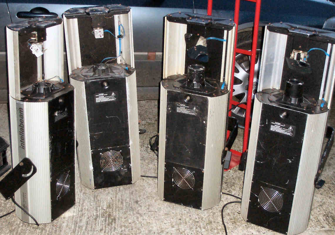
You've just got to love eBay haven't you? I found 6 High-End Intellabeam 400 scanners in a sorry state of repair, and snapped them all up for £75. One trip to Birmingham later, and I'm the proud owner of several hundredweight of scrap lighting. None of them had bulbs, some were missing boards, and the power supplies looked dangerous to say the least. Add to this the weight of the transformers in them, and it was starting to look like these were really beyond any use...
Now in their day, the Intellabeams were probably a bit special? DMX control, gobos, iris, shutter, dichroic filters, dimmable discharge bulbs...? These are all features you'd find on budget lights these days, but can you get 6 of them for £75? Probably not.
I spent many hours trying to resurrect the control boards on a couple of these lights, and I was able to get one up and running albeit with no bulb control - the 475W discharge bulbs were around £100 each and there was no guarantee that the high voltage parts would work or were even safe to power up. Some obvious problems showed up at this point, namely the DMX decoding was not very stable, and the amount of work required to get them all working seemed insurmountable. The solution - modernise them.
Things got so desparate at one point, I called a halt to the repairs and made a pointless video instead. Click here to watch the Intellabeams reluctantly stumble into life! (13Mb AVI file).
I was confident that I had enough working motor boards, so I set about redesigning the control systems. The first step was to disassemble the code in the EPROM and make sense of what was going on inside. Using a downloaded firmware upgrade file and some freeware disassemblers, I quickly learnt the 8051 architecture and decoded the assembly language to create this file. This is an unmodified version of the code with comments and appropriate variable names inserted - this took a very long time to work out and nearly resulted in the Intellabeams being thrown out of the window on more than one occasion!. However, after many long nights, here's the list of all of the various registers, and what I finally decided they were responsible for. While I was in the disassembly phase, I decoded all of the programmable logic into more understandable forms. This was mainly in case I needed to replace a GAL in the future.
The next step was to convert this code to a more familiar platform, and I chose the PIC 16F877 simply because I had several lying around. The resulting code and MPLAB project are here. The main stumbling blocks here are trying to work out the scaling algorithms used, and the comms protocol to talk to the motor board. The 16F877 code was compiled and the simulations were compared to what could be measured on the existing boards. I cannot emphasize enough how important it was to have a good oscilloscope and a logic analyser for this process. Thanks to HP/Agilent and goodbye Tektronix!
Now the point of all of this is to redesign the controller, so the next stage is to take this nasty assembler code, and convert it to nice easily modifiable C code. For this, I changed to the PIC18F452 processor so I could use the Microchip MCC18 C compiler. The code and project for this version can be downloaded here. This is now even more modified from the original version, and the IBeam's demo sequence has gone along with anything to do with the dimming of the discharge bulb since that circuit has been removed also. The DMX routines have been completely rewritten from scratch and have proved significantly more robust than the original code. One extra funtion has been added to DMX channel 8 of the fixture, which is a variable speed colour scroll. It only takes 4 lines of code to implement this function! Bulb dimming is now controlled by a simple 10V analogue dimmer module, and the PIC is able to output a PWM signal to control this. This is much simpler than the discharge bulb system, and it allows the use of cheap A1/244 500W quartz bulbs. A lookup table is provided to give S-curve dimming for smooth brightness fades from zero to full.
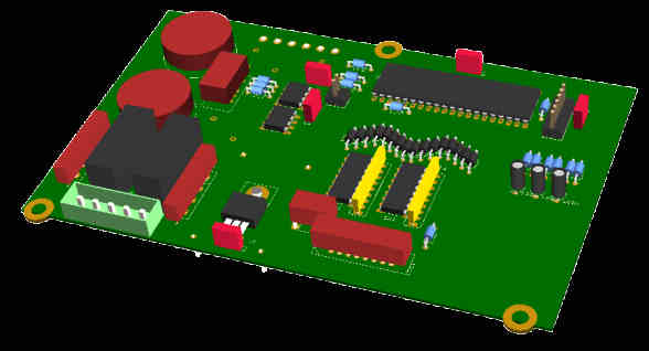
Here's the schematic of the PIC board in pdf, and a rough 3D model of it:
So if anyone out there has an old Inteallabeam that needs some TLC to get it working, just rip out the old board and power supplies and replace them with a nice light modern alternative. If anyone actually does this - please let me know! Thanks.
See also:
http://users.757.org/~ethan/lasers/ibeam/